Utilisateur:LMischler/Img-2018-P

De Guide de l'Installation Electrique
Aller à :navigation, rechercher
Fig. P1 – Installed photovoltaic capacity through 2016. Source: IEA-PVPS 2016 Snapshot of global Photovoltaic markets, April 2017 (DB431002_FR)
Fig. P2 – Evolution of feed-in-tariff rates and electricity price in Germany. Source: Recent Facts about Photovoltaics in Germany, Fraunhofer ISE, 2017 (DB431003_FR)
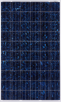
Fig. P3 – Photovoltaic cell manufactured in a silicon plate (source: Photowatt) (PB116820_FR)
Fig. P4 – Typical characteristic of a photovoltaic cell (DB422710_FR)
Fig. P5 – Irradiance and temperature influence the photovoltaic effect (DB422711_FR)
Fig. P6 – PW2300 photovoltaic module dimensions: 1638 x 982 x 40 mm (source: Photowatt) (PB116821_FR)
Fig. P9 – Conext CL60-A String inverter for Photovoltaic energy supply (DSC0755)
Fig. P10 – Operating point of a photovoltaic array which produces the most power, also known as the Maximum Power Point Tracker (DB422712_FR)
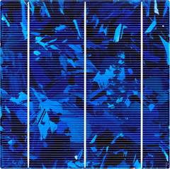
Fig. P12 – Reverse current (DB422713_FR)
Fig. P13 – String overcurrent protection “OCP” (DB422714_FR)
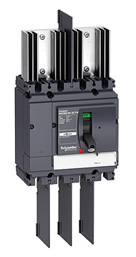
Fig. P14 – Switch-disconnector Compact NSX 200A with heatsink and interphase barrier (PB116823)
Fig. P15 – Switch-disconnector location (DB422715_FR)
Fig. P16 – Avoiding loops when cabling strings (DB422718_FR)
Fig. P17 – Diagram showing a single-string photovoltaic array (DB422719_FR)
Fig. P18 – Diagram showing a multi-string photovoltaic array with one inverter (DB422720_FR)
Fig. P19 – Diagram showing a multi-string photovoltaic array with several single-phase inverters connected in a three-phase arrangement (DB422721_FR)
Fig. P20 – Diagram showing a photovoltaic array consisting of several groups (DB422722_FR)
Fig. P21 – Exemple of architecture based on "PV AC modules" (DB431008_FR)
Fig. P22 – Grid connected y 10kW (DB422723_FR)
Fig. P23 – 10-100kW single MPPT inverter (DB422725_FR)
Fig. P24 – 10-100kW multi single MPPT inverter (DB422726_FR)
Fig. P25 – 150-500 kW single MPPT inverter with N arrays > 2 (DB422728_FR)
Fig. P26 – PV installation connected to the main LV Switchboard (DB431004_FR)
Fig. P27 – PV installation connected to secondary LV switchboards (DB431005_FR)
Fig. P28 – PV installation connected upstream to the main LV switchboard (DB431006_FR)
Fig. P29 – PV installation connected upstream to the main LV switchboard (DB431007_FR)
Fig. P30 – Monitoring system for commercial PV installations (DB431030_FR)
Fig. P31 – Example of a system for remote monitoring used in utility-scale power plants (DB422732_FR)